How to set up a WebFront
in IP-Symcon to control a Xcomfort system
·
Open
the “IP-Symcon Management Console”
·
First
you need to make sure the IPSymcon WebServer is running. This is done by
clicking on the “Logical Treeview”
link

·
Navigate
to the “Core Instances” and check
that there is a component called “WebInterface
WebFront”. Double click on this to open the property page.

·
Verify
that the server is running and that it is configured to listed to “All” addresses and that the Port is set
to a TCP port that is not in use (default is 82). Make a note of the port value as we will configure the
firewall later to allow incoming traffic to this port. If you made any changes
then click [Apply]

·
Next
you need to organize all the XComfort components into a logical structure.
·
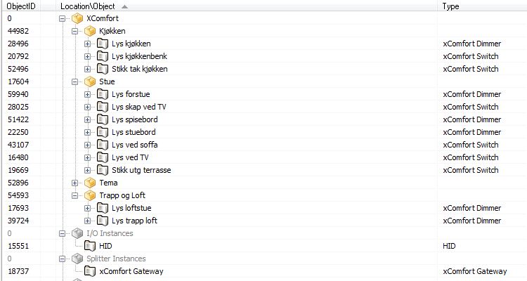
Still
in the “Logical Treeview” window. As
shown in the example below I have created a set of Catagories and placed the XComfort components (and some PHP
scripts) into a desired logical structure. You add a new Category by right
click a node and select “Add Object – Add
Category”

·
Now,
close the “Logical Treeview” window
and return to the main windows in IPSymcon
·
Normally
IPSymcon is installed with a default web front. I will now add an additional WebFront
only for the XComfort components show above. Click on the “Configure WebFront” link

·
Click
on the [New] button

·
A
default WebFront is created with some basic items in it. In this example I will
not make many adjustments to this, but there is a lot of configuration you can
do to build quite advanced web pages to control various events and components.
·
Double
click on the “Category” item to open
the properties page

·
Click
on the number 0 value in the “Root” property.

·
A
location tree will now appear. Select the root level of the XComfort devices
you want to add by double click on it (in my example it is the “Lys” with ObjectID 42817)

·
Back
in the Category properties window, verify that the root value have changed to
the ObjectID that you selected (in my example this is 42817). Click [OK]

·
Back
in the WebFront config window, click [Apply]

·
Click
on the “Appearance” TAB and e.g
specify the name “XComfort” in the
Title field . Click [Apply]

·
If
you are using the Android or iOS app from IPSymcon then click on the “Mobile/Retro” TAB and configure as
shown below. Click [OK] and [Apply] when done

·
You
may also want to protect the access to this configuration with a password. You
do this by clicking on the “Security”
TAB and specify a password. This is especially important if you publish this
configuration towards Internet in your internet router (e.g if you want to control
the WebFront from the mobile app and/or a browser outside your home).
·
OK,
almost there. You can now close the WebFront configurator and return to the
main window in IP Symcon and then close the IP Symcon console
·
Finalize
the setup by configure the Windows firewall. Open the windows Firewall
management console (in Windows 7 and Windows Server 2008 R2 this is called “Windows Firewall with Advanced Security”
·
Click
on the “Inbound” node and click “New Rule” in the action pane:
o
Select
“Port”
o
Select
“TCP” and then specify the port 82 (same as the IPSymcon WebServer is
running on as shown previously in this procedure)
o
Select
“Allow the connection”
o
Select
“Domain”, “Private” and “Public”
o
Type
a name for the rule
o
Click
[Finish]
·
Now
test the new WebFront by open an internet explorer e.g Chrome (do not use IE as
this does not work properly with IPSymcon) and specify the URL:
http://<ip address of your machine>:82
http://<ip address of your machine>:82
·
You
should now see the IPSymcon welcome page and a link called “XComfort” (if you used that name on the
WebFront previously) at the front page. The “Login” is another WebFront that I
have in my system.

·
Click
on the XComfort link and specify the
password (if that was configured previously). The web page (WebFront) is now
shown and you have a menu item corresponding to the logical structure of your
XComfort devices as configured in the IPSymcon logical treeview.

·
If
you need access from Internet, then publish this IP and port through your
Internet router. I will not go into details how this is done as this varies quite
a bit from router to router. See the internet router documentation for instructions
how to do this.
·
If
you are using the IPSymcon mobile app, then configure this to point to the same
IP and port as shown above (or the NAT ip address of your internet router). You
will then get the same logical structure on the mobile device as shown in the
browser above. I know the app cost a bit, but I can strongly recommend it.
·
Enjoy!